Binary Heap | Binomial Heap | Fibonacci Heap (M5)

Binary Heap

A Binary Heap is a Binary Tree with following properties.

  1. It’s a complete binary tree (all levels are completely filled except possibly the last level and the last level has all keys as left as possible). This property of Binary Heap makes them suitable to be stored in an array.
  2. A Binary Heap is either Min Heap or Max Heap. In a Min Binary Heap, the key at root must be minimum among all keys present in Binary Heap. The same property must be recursively true for all nodes in Binary Tree. Max Binary Heap is similar to Min Heap.

 
A complete binary tree is a binary tree in which all the levels are completely filled except possibly the lowest one, which is filled from the left.

A binary tree is a tree-type non-linear data structure with a maximum of two children for each parent. Every node in a binary tree has a left and right reference along with the data element. The node at the top of the hierarchy of a tree is called the root node. The nodes that hold other sub-nodes are the parent nodes.

 Binomial Heap

A Binomial Heap is a collection of Binomial Tree where each Binomial Tree follows the Min-Heap property and there can be at most one Binomial Tree of any degree.

The binomial tree Bk is an ordered tree defined recursively, the binomial tree B0 consists of a single node. The binomial tree Bk consists of two binomial trees Bk -1 that are linked together so that the root of one is the leftmost child of the root of the other.

Fibonacci Heap


A Fibonacci heap is a specific implementation of the heap data structure that makes use of Fibonacci numbers. Like Binomial Heap, Fibonacci Heap is a collection of trees with Min-Heap or Max-Heap property. 

In Fibonacci Heap, trees can have any shape even all trees can be single nodes (This is unlike Binomial Heap where every tree has to be a Binomial Tree). 

 Fibonacci Heap maintains a pointer to a minimum value (which is the root of a tree). All tree roots are connected using a circular doubly linked list, so all of them can be accessed using a single ‘min’ pointer.

Like binomial heaps, Fibonacci heaps use doubly linked lists to allow for O(1)O(1) time for operations such as splicing off a part of a list, merging two lists, and finding the minimum (or maximum) value. Each node contains a pointer to its parent and any one of its children. The children are all linked together in a doubly linked list called the child list. Each child in the child list has pointers for its left sibling and its right sibling.

For each node, the linked list also maintains the number of children a node has, a pointer to the root containing the minimum key, and whether the node is marked. A node is marked to indicate that it has lost a single child and a node is unmarked if it loses no children. See the description of the decrease-key function in the next section for more details. 

Fibonacci Heap | Set 1 (Introduction) - GeeksforGeeks

Advantages:

Fibonacci heaps are used to implement the priority queue element in Dijkstra’s algorithm, giving the algorithm a very efficient running time. 

Fibonacci heaps have a faster amortized running time than other heap types. Fibonacci heaps are similar to binomial heaps but Fibonacci heaps have a less rigid structure. 

Binomial heaps merge heaps immediately but Fibonacci heaps wait to merge until the extract-min function is called.


 https://brilliant.org/wiki/fibonacci-heap/

https://brilliant.org/wiki/binomial-heap/

Three Tier Client Server Architecture (M3.3)

A 3 Tier Architecture in DBMS is the most popular client server architecture in DBMS in which the development and maintenance of functional processes, logic, data access, data storage, and user interface is done independently as separate modules.

3-Tier database Architecture design is an extension of the 2-tier client-server architecture. A 3-tier architecture has the following layers:

  1. Presentation layer (your PC, Tablet, Mobile, etc.)
  2. Application layer (server)
  3. Database Server

The chief benefit of three-tier architecture is that because each tier runs on its own infrastructure, each tier can be developed simultaneously by a separate development team, and can be updated or scaled as needed without impacting the other tiers.

Presentation tier

  • The presentation tier is the user interface and communication layer of the application, where the end user interacts with the application. 
  • Its main purpose is to display information to and collect information from the user. 
  • This top-level tier can run on a web browser, as desktop application, or a graphical user interface (GUI), 
  • For example. Web presentation tiers are usually developed using HTML, CSS and JavaScript. Desktop applications can be written in a variety of languages depending on the platform.

Application tier

  • The application tier, also known as the logic tier or middle tier, is the heart of the application. 
  • In this tier, information collected in the presentation tier is processed - sometimes against other information in the data tier - using business logic, a specific set of business rules. 
  • The application tier can also add, delete or modify data in the data tier.

The application tier is typically developed using Python, Java, Perl, PHP or Ruby, and communicates with the data tier using API calls. 

Data tier

  • The data tier, sometimes called database tier, data access tier or back-end, is where the information processed by the application is stored and managed.
  • This can be a relational database management system such as PostgreSQL, MySQL, MariaDB, Oracle, DB2, Informix or Microsoft SQL Server, or in a NoSQL Database server such as Cassandra, CouchDB or MongoDB. 

In a three-tier application, all communication goes through the application tier. The presentation tier and the data tier cannot communicate directly with one another.

The goal of Three Tier client-server architecture is:

  • To separate the user applications and physical database
  • To support DBMS characteristics
  • Program-data independence
  • Supporting multiple views of the data

Benefits of three-tier architecture

Again, the chief benefit of three-tier architecture its logical and physical separation of functionality. Each tier can run on a separate operating system and server platform - e.g., web server, application server, database server - that best fits its functional requirements. And each tier runs on at least one dedicated server hardware or virtual server, so the services of each tier can be customized and optimized without impact the other tiers. 

Other benefits (compared to single- or two-tier architecture) include:

  • Faster development: Because each tier can be developed simultaneously by different teams, an organization can bring the application to market faster, and programmers can use the latest and best languages and tools for each tier.
  • Improved scalability: Any tier can be scaled independently of the others as needed.
  • Improved reliability: An outage in one tier is less likely to impact the availability or performance of the other tiers.
  • Improved security: Because the presentation tier and data tier can't communicate directly, a well-designed application tier can function as a sort of internal firewall, preventing SQL injections and other malicious exploits.
 A 'layer' refers to a functional division of the software, but a 'tier' refers to a functional division of the software that runs on infrastructure separate from the other divisions. The Contacts app on your phone, for example, is a three-layer application, but a single-tier application, because all three layers run on your phone.


Concurrency Control in Distributed Db (M3.2)

 Concurrency controlling techniques ensure that multiple transactions are executed simultaneously while maintaining the ACID properties of the transactions and serializability in the schedules.

Concurrency control is provided in a database to:

  • enforce isolation among transactions.
  • preserve database consistency through consistency preserving execution of transactions.
  • resolve read-write and write-read conflicts

Various approaches for concurrency control

 1. Locking Protocols (Locking Based Concurrency Control Protocols)

Locking-based concurrency control protocols use the concept of locking data items. A lock is a variable associated with a data item that determines whether read/write operations can be performed on that data item. Generally, a lock compatibility matrix is used which states whether a data item can be locked by two transactions at the same time.

Locking-based concurrency control systems can use either one-phase or two-phase locking protocols.

1.1 Single Lock-Manager Approach 

In the single lock-manager approach, the system maintains a single lock manager
that resides in a single chosen site. 

In this method, each transaction locks an item before use and releases the lock as soon as it has finished using it. This locking method provides for maximum concurrency but does not always enforce serializability.

Advantages:

  • Simple implementation. This scheme requires two messages for handling lock requests and one message for handling unlock requests. 
  • Simple deadlock handling. Since all lock and unlock requests are made at one site.
 Disadvantages 

• Bottleneck. The site Si becomes a bottleneck, since all requests must be processed there.
• Vulnerability. I
f the site S i fails, the concurrency controller is lost. Either
processing must stop, or a recovery scheme must be used so that a backup
site can take over lock management from S i.

1.2 Distributed Lock Manager

1.3 Primary Copy

1.4 Majority Protocol

1.5 Biased Protocol

1.6 Quorum Consensus Protocol

2. Time-stamping

3. Replication with Weak Degrees of Consistency 

4. Deadlock Handling


Commit Protocols- 2Phase & 3Phase (M3.1)

Commit Protocols are used to ensure atomicity, across the sites in which a transaction T executed must either commit at all sites, or it must abort at all sites. To ensure this property, the transaction coordinator(manages distributed transactions) of T, must execute a commit protocol.

Among the simplest and most widely used commit protocols is the two-phase
commit protocol (2PC).

An alternative is the three-phase commit protocol (3PC) , which avoids certain disadvantages of the 2PC protocol but adds to complexity and overhead.

Atomicity: The term atomicity defines that the data remains atomic. It means if any operation is performed on the data, either it should be performed or executed completely or should not be executed at all. It further means that the operation should not break in between or execute partially.

Two-phase commit

In the Two-phase commit protocol, there are two phases (that’s the reason it is called Two-phase commit protocol) involved. The first phase is called prepare. In this phase, a coordinator (either a separate node or the node initiating the transaction) makes a request to all the participating nodes, asking them whether they are able to commit the transaction. They either return yes or no in the response. They return yes if they can successfully commit the transaction or no if they unable to do so.

In the second phase, coordinator decides based on the votes whether to send the commit or abort request to the participating nodes. This phase is called the commit phase.

  • If all the participating nodes said yes, then commit request is sent to all the nodes
  • If any of the participating nodes said no, then abort request is sent to all the nodes

Microservices: It's not (only) the size that matters, it's (also) how you  use them – part 2 – Jeppe Cramon's Software development blog 

Advantages

  • The two phase commit protocol is a distributed algorithm which lets all sites in a distributed system agree to commit a transaction.  
  • The protocol results in either all nodes committing the transaction or aborting, even in the case of site failures and message losses.

Disadvantages

  • The greatest disadvantage of the two-phase commit protocol is that it is a blocking protocol. If the coordinator fails permanently, some participants will never resolve their transactions: After a participant has sent an agreement message to the coordinator, it will block until a commit or rollback is received.  

 Handling of Failures

The 2PC protocol responds in different ways to various types of failures:


Failure of a participating site

If the coordinator C i detects that a site has failed, it takes these actions: If the site fails before responding with a ready T message to C i , the coordinator assumes that it responded with an abort T message. If the site fails after the coordinator has received the ready T message from the site, the coordinator executes the rest of the commit protocol in the normal fashion, ignoring the failure of the site.

Let T be one such transaction. We consider each of the possible cases:

  • The log contains a <commit T> record. In this case, the site executes redo(T). 
  • The log contains an <abort T> record. In this case, the site executes
    undo(T).
  • The log contains a <ready T> record. In this case, the site must consult C i to determine the fate of T.  
  • The log contains no control records (abort, commit, ready) concerning T.

Failure of the coordinator

If the coordinator fails in the midst of the execution of the commit protocol for transaction T, then the participating sites must decide the fate of T. 

We shall see that, in certain cases, the participating sites cannot decide whether to commit or abort T, and therefore these sites must wait for the recovery of the failed coordinator.

  •  If an active site contains a <commit T> record in its log, then T must be committed. 
  • If an active site contains an <abort T> record in its log, then T must be aborted. 
  • If some active site does not contain a <ready T> record in its log, then
    the failed coordinator C i cannot have decided to commit T  because a site
    that does not have a <ready T> record in its log cannot have sent a ready
    T message to C i . However, the coordinator may have decided to abort T,
    but not to commit T. Rather than wait for C i to recover, it is preferable to
    abort T.
  • If none of the preceding cases holds, then all active sites must have a
    <ready T> record in their logs, but no additional control records (such as <abort T> or <commit T>). Since the coordinator has failed, it is
    impossible to determine whether a decision has been made, and if one
    has, what that decision is, until the coordinator recovers. Thus, the active
    sites must wait for C i to recover. Since the fate of T remains in doubt, T may
    continue to hold system resources. For example, if locking is used, T may
    hold locks on data at active sites. Such a situation is undesirable, because
    it may be hours or days before C i is again active. During this time, other
    transactions may be forced to wait for T. As a result, data items may be
    unavailable not only on the failed site (C i ), but on active sites as well. This
    situation is called the blocking problem, because T is blocked pending
    the recovery of site C i .

Network partition

When a network partitions, two possibilities exist:


1. The coordinator and all its participants remain in one partition. In this
case, the failure has no effect on the commit protocol.


2. The coordinator and its participants belong to several partitions. From
the viewpoint of the sites in one of the partitions, it appears that the
sites in other partitions have failed. Sites that are not in the partition
containing the coordinator simply execute the protocol to deal with
failure of the coordinator. The coordinator and the sites that are in the
same partition as the coordinator follow the usual commit protocol,
assuming that the sites in the other partitions have failed.


Thus, the major disadvantage of the 2PC protocol is that coordinator failure may result in blocking, where a decision either to commit or to abort T may have to be postponed until C i recovers.

Two Phase Commit (2PC) is one of the failure recovery protocols commonly used in distributed database management system. It has a disadvantage of getting blocked under certain circumstances. For example, assume a case where the coordinator of a particular transaction is failed, and the participating sites have all sent <READY T> message to the coordinator. Now, participating sites do not have either <ABORT T> or <COMMIT T>. At this stage, no site can take a final decision on its own. Only solution is to wait for the recovery of the coordinator site. Hence, 2PC is a blocking protocol.

Three Phase Commit (3PC) Protocol

 3PC is a protocol that eliminates this blocking problem on certain basic requirements;

  • No network partitioning
  • At least one site must be available
  • At most K simultaneous site failures are accepted
2PC has two phases namely voting phase and decision phase. 3PC introduces pre-commit phase (serves as a buffer phase) as the third phase.


3PC works as follows;

Phase 1 (WAIT/VOTING):
Transaction Coordinator (TC) of the transaction writes BEGIN_COMMIT message in its log file and sends PREPARE message to all the participating sites and waits.
Upon receiving this message, if a site is ready to commit, then the site’s transaction manager (TM) writes READY in its log and send VOTE_COMMIT to TC.
If any site is not ready to commit, it writes ABORT in its log and responds with VOTE_ABORT to the TC.

Phase 2 (PRE-COMMIT):
If TC received VOTE_COMMIT from all the participating sites, then it writes PREPARE_TO_COMMIT in its log and sends PREPARE_TO_COMMIT message to all the participating sites.
On the other hand, if TC receives any one VOTE_ABORT message, it writes ABORT in its log and sends GLOBAL_ABORT to all the participating sites and also writes END_OF_TRANSACTION message in its log.
On receiving the message PREPARE_TO_COMMIT, the TM of participating sites write PREPARE_TO_COMMIT in their log and respond with READY_TO_COMMIT message to the TC.
If they receive GLOBAL_ABORT message, then TM of the sites write ABORT in their logs and acknowledge the abort. Also, they abort that particular transaction locally.

Phase 3 (COMMIT/DECIDING):
If all responses are READY_TO_COMMIT, then TC writes COMMIT in its log and send GLOBAL_COMMIT message to all the participating sites’ TMs. The TM of those sites then writes COMMIT in their log and sends an acknowledgement to the TC. Then, TC writes END_OF_TRANSACTION in its log.
  6: 3-Phase Commit Protocol | Download Scientific Diagram

Advantages of 3PC Protocol

  • The Blocking problem found in 2PC can be avoided (in certain occasions, especially when at least not more than k sites failed)

Disadvantages of 3PC Protocol

  • Network partitions (network segments) would cause Blocking Problem, especially if more than k sites are part of any partitions.  
  • Long latency due to the number of messages to be transferred between sites on taking decision. That is, it involves 3 phases and all the 3 phases involve communication between sites.


B Tree & B+ Tree

B TREE

  • It is a generalized form of the binary search tree / Extension of BST / Special type of BST
  • It is also known as a height-balanced m-way search tree.
  • B-tree is a special type of self-balancing search tree in which each node can contain more than one key and can have more than two children.  (i.e. if there is n children, there can be n-1 keys) 
    • NOTE: the no. of keys in a node & no. of children for a node depends on the order of B Tree. Every B Tree has a order m.
     
  • Desined to work well on disks or other direct access secondary devices.
  • Better at minimizing disk i/o operations. 

Why B-tree?

As we have said, B Tree is mainly used for disk access,So The need for B-tree arose with the rise in the need for accessing the physical storage media like a hard disk in less time. Even though, The secondary storage devices have larger capacity, they are slower in processing. There was a need for such types of data structures that minimize the disk accesses.

Other data structures such as a binary search tree, avl tree, red-black tree, etc can store only one key in one node. If you have to store a large number of keys, then the height of such trees becomes very large and the access time increases.

However, B-tree can store many keys in a single node and can have multiple child nodes. This decreases the height significantly allowing faster disk accesses.

One of the main reason of using B tree is its capability to store large number of keys in a single node and large key values by keeping the height of the tree relatively small.

B-tree Properties

1. All leaf nodes must be at the same level. 

2. If n is the order of the tree, each internal node can contain at most n - 1 keys & have n no. of children.

3. Each node except root can have at most n children and at least n/2 children. 

4. The root has at least 2 children and contains a minimum of 1 key.

5. All nodes except root must have at least n/2 -1 keys & maximum of n-1 keys. 

6. All the key values in a node must be in Ascending Order.

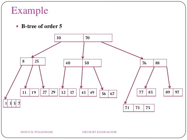
For example, the following is an order-5 B-tree (m=5)

B-trees 

Multi ways trees

While performing some operations on B Tree, if any property of B Tree may get  violated (like min no. of nodes), so in that case we maintain the properties of B Tree, by borrowing from the immediate left or right node, or merging the nodes. 

Applications

Storing blocks of data: B tree is used to index the data and provides fast access to the actual data stored on the disks since, the access to value stored in a large database that is stored on a disk is a very time consuming process.

Multilevel Indexing: Searching an un-indexed and unsorted database containing n key values needs O(n) running time in worst case. However, if we use B Tree to index this database, it will be searched in O(log n) time in worst case.


Complexities

Worst case Time complexity: Θ(log n)

Average case Time complexity: Θ(log n)

Best case Time complexity: Θ(log n)

Average case Space complexity: Θ(n)

Worst case Space complexity: Θ(n)


B+ TREE 

 
B+ Tree is an extension of B Tree which allows efficient insertion, deletion and search operations. 

A B+ tree is an advanced form of a self-balancing tree in which all the values are present in the leaf level.

A B+ Tree is primarily utilized for implementing dynamic indexing on multiple levels. Compared to B- Tree, the B+ Tree stores the data pointers only at the leaf nodes of the Tree, which makes search more process more accurate and faster. 

The leaf nodes of a B+ tree are linked together in the form of a singly linked lists to make the search queries more efficient. 

An important concept to be understood before learning B+ tree is multilevel indexing. In multilevel indexing, the index of indices is created as in figure below. It makes accessing the data easier and faster.

Multilevel Indexing using B+ tree 

B+ Tree are used to store the large amount of data which can not be stored in the main memory. Due to the fact that, size of main memory is always limited, the internal nodes (keys to access records) of the B+ tree are stored in the main memory whereas, leaf nodes are stored in the secondary memory.

The internal nodes of B+ tree are often called index nodes. 

WHY B+Tree

  • Key are primarily utilized to aid the search by directing to the proper Leaf.
  • B+ Tree uses a "fill factor" to manage the increase and decrease in a tree.
  • In B+ trees, numerous keys can easily be placed on the page of memory because they do not have the data associated with the interior nodes. Therefore, it will quickly access tree data that is on the leaf node.
  • A comprehensive full scan of all the elements is a tree that needs just one linear pass because all the leaf nodes of a B+ tree are linked with each other.


Properties of a B+ Tree

  1. All leaves are at the same level.
  2. The root has at least two children.
  3. Each node except root can have a maximum of m children and at least m/2 children.
  4. Each node can contain a maximum of m - 1 keys and a minimum of ⌈m/2⌉ - 1 keys.


Advantages of B+ Tree

  1. Records can be fetched in equal number of disk accesses.
  2. Height of the tree remains balanced and less as compare to B tree.
  3. We can access the data stored in a B+ tree sequentially as well as directly.
  4. Keys are used for indexing.
  5. Faster search queries as the data is stored only on the leaf nodes.


B+ Tree Applications

  • Multilevel Indexing
  • Faster operations on the tree (insertion, deletion, search)
  • Database indexing

Difference bw B Tree & B+ Tree

In a B tree, search keys and data stored in internal or leaf nodes, whereas In a B+ tree, data stored only in leaf nodes.

The leaves are not connected with each other on a B-tree whereas they are connected on a B+ tree.

Operations on a B+ tree are faster than on a B-tree,  searching of any data in a B+ tree is very easy because all data is found in leaf nodes.


Monk and Inversions

using System; public class Solution { public static void Main () { int T = Convert . ToInt32 ( Console . ReadLine...