Network Edge
- It actually refers to the end of the network.
- This network consists of edge devices such as computers, WiFi access points, and other devices which are also known as hosts or end systems, that are connected at the edge of the network.
- End systems are referred to as hosts because they host (that is, run) application programs such as a Web browser program, a Web server program, an e-mail client program, or an e-mail server program.
- Hosts are sometimes further divided into two categories: clients and servers.
- Informally,clients tend to be desktop and mobile PCs, smartphones, and so on, whereas servers tend to be more powerful machines that store and distribute Web pages, stream video, relay e-mail, and so on.
- Today, most of the servers from which we receive search results, e-mail, Web pages, and videos reside in large data centers. For example, Google has 30–50 data centers, with many having more than one hundred thousand servers.
- Network Edge is the point at which the enterprise-owned network connects to a third-party network.
- It is also referred to as the one or more boundaries within a network that designate who controls the underlying network infrastructure equipment.
Access network—the network that physically connects an endsystem to the first router (also known as the “edge router”) on a path from the end system to any other distant end system.
Home Access
The two most prevalent types of broadband residential access are Digital subscriber line (DSL) and cable.
A residence typically obtains DSL Internet access from the same local telephone company (telco) that provides its wired local phone access. Thus, when DSL is used, a customer’s telco is also its ISP.
On the customer side, a splitter separates the data and telephone signals arriving to the home and forwards the data signal to the DSL modem.
On the telco side, in the CO, the DSLAM separates the data and phone signals and sends the data into the Internet. Hundreds or even thousands of households connect to a single DSLAM.
While DSL makes use of the telco’s existing local telephone infrastructure, cable Internet access makes use of the cable television company’s existing cable television infrastructure.
A residence obtains cable Internet access from the same company that provides its cable television.
- Fiber optics connect the cable head end to neighborhood-level junctions, from which traditional coaxial cable is then used to reach individual houses and apartments.
- Each neighborhood junction typically supports 500 to 5,000 homes.
- Because both fiber and coaxial cable are employed in this system, it is often referred to as hybrid fiber coax (HFC).
Cable internet access requires special modems, called cable modems. As with a DSL modem, the cable modem is typically an external device and connects to the home PC through an Ethernet port.
One important characteristic of cable Internet access is that it is a shared broadcast medium.
- In particular, every packet sent by the head end travels down-stream on every link to every home and every packet sent by a home travels on the upstream channel to the head end.
- For this reason, if several users are simultaneously downloading a video file on the downstream channel, the actual rate at which each user receives its video file will be significantly lower than the aggregate cable downstream rate.
- On the other hand, if there are only a few active users and they are all Web surfing, then each of the users may actually receive Web pages at the full cable downstream rate, because the users will rarely request a Web page at exactly the same time.
- Because the upstream channel is also shared, a distributed multiple access protocol is needed to coordinate transmissions and avoid collisions.
Access in the Enterprise (and the Home): Ethernet and WiFi
- On corporate and university campuses, and increasingly in home settings, a local areanetwork (LAN) is used to connect an end system to the edge router.
- Although there are many types of LAN technologies,
- Ethernet is by far the most prevalent access technology in corporate, university, and home networks.
- Even though Ethernet and WiFi access networks were initially deployed in enter-prise (corporate, university) settings, they have recently become relatively common components of home networks.
- Many homes combine broadband residential access(that is, cable modems or DSL) with these inexpensive wireless LAN technologies to create powerful home networks
Wide-Area Wireless Access: 3G and LTE
- Increasingly, devices such as iPhones, BlackBerrys, and Android devices are being used to send email, surf the Web, Tweet, and download music while on the run.
- These devices employ the same wireless infrastructure used for cellular telephony to send/receive packets through a base station that is operated by the cellular net-work provider.
- Unlike WiFi, a user need only be within a few tens of kilometers (as opposed to a few tens of meters) of the base station.
- Telecommunications companies have made enormous investments in so-called third-generation (3G) wireless, which provides packet-switched wide-area wireless Internet access at speeds in excess of 1 Mbps. But even higher-speed wide-areaaccess technologies—a fourth-generation (4G) of wide-area wireless networks—arealready being deployed.
- LTE ( for “Long-Term Evolution”—a candidate for BadAcronym of the Year Award) has its roots in 3G technology, and can potentiallyachieve rates in excess of 10 Mbps
Physical Media
Physical media refers to the physical materials that are used to store or transmit information in data communications.
Examples of physical media include twisted-pair copper wire, coaxial cable, multimode fiber-optic cable, terrestrial radio spectrum, and satellite radio spectrum.
Physical media fall into two categories: guided media and unguided media.
With guided media, the waves are guided along a solid medium, such as a fiber-optic cable, a twisted-paircopper wire, or a coaxial cable.
With unguided media, the waves propagate in theatmosphere and in outer space, such as in a wireless LAN or a digital satellitechannel.
#Twisted-Pair Copper Wire
- The least expensive
- Most commonly used guided transmission medium
- Consists of two insulated copper wires, arranged in a regular spiral pattern.
- The wires are twisted together to reduce the electrical interference from similar pairs close by.
- Typically, a number of pairs are bundled together in a cable by wrapping the pairs in a protective shield.
- A wire pair constitutes a single communication link. Unshielded twisted pair (UTP)is commonly used for
#Coaxial Cable
- Like twisted pair, coaxial cable consists of two copper conductors, but the two conductors are concentric rather than parallel.
- With this construction and special insulation and shielding, coaxial cable can achieve high data transmission rates.
- Coaxial cable is quite common in cable television systems.
- Coaxial cable can be used as a guided shared medium.
- Specifically, a number ofend systems can be connected directly to the cable, with each of the end systems receiving whatever is sent by the other end systems.
#Fiber Optics
- An optical fiber is a thin, flexible medium that conducts pulses of light, with eachpulse representing a bit.
- A single optical fiber can support tremendous bit rates, upto tens or even hundreds of gigabits per second.
- They are immune to electromag-netic interference, have very low signal attenuation up to 100 kilometers, and arevery hard to tap.
- These characteristics have made fiber optics the preferred long-haul guided transmission media, particularly for overseas links
#Terrestrial Radio Channels
- Radio channels carry signals in the electromagnetic spectrum.
- They are an attractive medium because they require no physical wire to be installed, can penetrate walls,provide connectivity to a mobile user, and can potentially carry a signal for long distances.
- The characteristics of a radio channel depend significantly on the propagation environment and the distance over which a signal is to be carried.
#Satellite Radio Channels
- A communication satellite links two or more Earth-based microwave transmitter/receivers, known as ground stations.
- The satellite receives transmissions on one fre-quency band, regenerates the signal using a repeater (discussed below), and transmitsthe signal on another frequency.
- Two types of satellites are used in communications:geostationary satellitesandlow-earth orbiting (LEO) satellites.
Types of Network Architecture used:
- Peer to Peer- In Peer-to-peer networks computers are connected to each other so that each computer can share its resources and information. It does not contain a centralized system.
- Client-Server- In Client-server networks there is a central controller which is known as a server which is responsible for managing all the resources while all other computers in the network are called clients. All the clients communicate with each other through a server.
For example, if client1 wants to send some data to client 2, then it first sends the request to the server for the permission. The server sends the response to the client 1 to initiate its communication with the client 2.
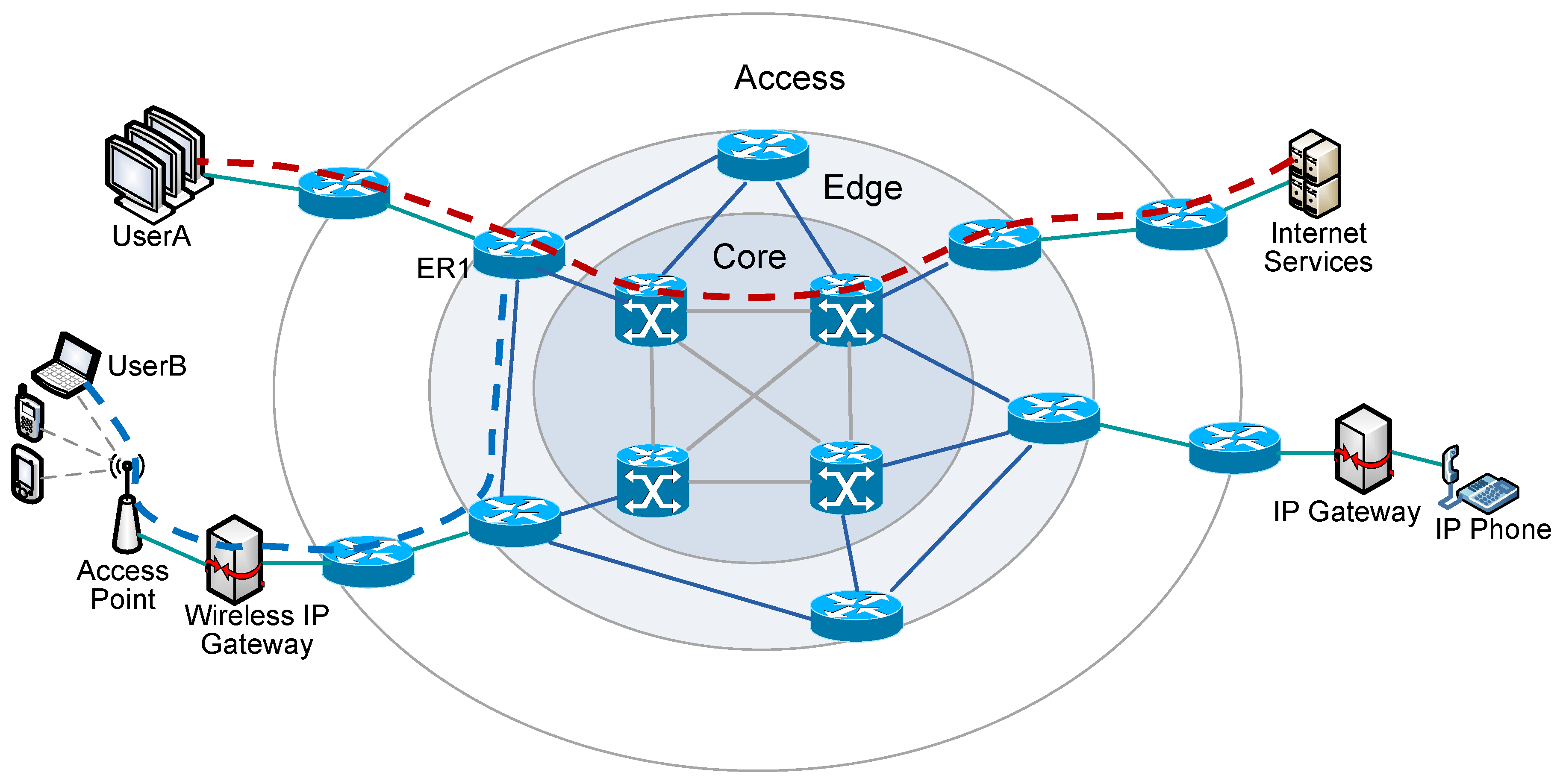
Network Core
The mesh of packet switches and links that interconnects the Internet’s end systems.
- In simple, It is a mesh of routers.
- Network core functions to interconnect various parts of a network.
- It provides a path for the exchange of information within the data centre and between other data centres via routers and switches.
- Network core functionality includes aggregation, authentication, call control/switching, charging, gateways, and service invocation.
- Network cores are categorized as collapsed, parallel, or serial.
Switching is the technique by which nodes control or switch data to
transmit it between specific points on a network. There are 3 common
switching techniques:
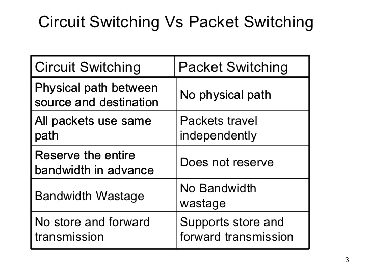
- Circuit Switching
- Packet Switching
- Message Switching- Message switching was a technique developed as an alternate to circuit
switching, before packet switching was introduced. In message switching,
end users communicate by sending and receiving messages that included the entire data to be shared.
Data is transferred through the net by,
#Packet Switching
- Packet Switching transmits
data across digital networks by breaking it down into blocks or packets
for more efficient transfer using various network devices.
- Each time
one device sends a file to another, it breaks the file down into packets
so that it can determine the most efficient route for sending the data
across the network at that time.
- The network devices can then route the
packets to the destination where the receiving device reassembles them
for use.
- These data chunks or “packets” allow for faster, more
efficient data transfer.
Often, when a user sends a file across a
network, it gets transferred in smaller data packets, not in one piece.
For example, a 3MB file will be divided into packets, each with a packet
header that includes the origin IP address, the destination IP address,
the number of packets in the entire data file, and the sequence number.
What is Packet Loss?
Occasionally,
packets might bounce from router to router many times before reaching
their destination IP address. Enough of these kinds of “lost” data
packets in the network can congest it, leading to poor performance. Data
packets that bounce around in the network too many times may get lost.
The
hop count addresses this problem, setting a maximum number of bounce
times per packet. “Bouncing” simply refers to the inability to locate
the final destination IP address, and the resulting transfer from one
router to another instead. If a certain packet reaches its maximum hop
count, or maximum number of hops it is permitted before reaching its
destination, the router it is bouncing from deletes it. This causes
packet loss.
Advantages of Packet Switching over Circuit Switching
Efficiency.
Improved efficiency means less network bandwidth wastage. No need to
reserve the circuit even when it’s not in use means the system is more
efficient. A constantly reserved circuit results in wasted network
bandwidth, so network efficiency tends to increase with the use of
packet switching.
Speed. Optimal transmission speed, minimal latency.
Improved fault tolerance.
During partial outages or other network problem times, packets can be
rerouted and follow different paths. Using a circuit switching network, a
single outage can down the designated pathway for the communications.
Budget.
Comparatively cost-effective and simple to implement. Packet switching
typically also bills based only on duration of connectivity, whereas
circuit switching bills on both duration of connection and distance.
Digital.
Packet switching works well for data communication, transmitting
digital data directly to its destination. Data transmissions are
generally high quality in a packet switched network because such a
network employs error detection and checks data distribution with the
goal of error free transmissions.
Disadvantages of Packet Switching over Circuit Switching:
Reliability.
The packet switching process is reliable in that the destination can
identify any missing packets. However, circuit switched networks deliver
packets in order along the same route and are therefore less likely to
experience missing packets in the first place.
Complexity. Packet switching protocols are complex, so switching nodes demand more processing power and a large amount of RAM.
File size.
Packet switching is more useful for small messages, while circuit
switching is best for larger transmissions. This is due to multiple
rerouting delays, the risk of multiple lost packets, and other issues.
Store-and-Forward Transmission
Most packet switches use store-and-forward transmission at the inputs to the links. Store-and-forward transmission means that the packet switch must receive the entire packet before it can begin to transmit the first bit of the packet onto the outbound link.
#Circuit switching
- Circuit switching is a switching technique that establishes a dedicated path between sender and receiver.
- In the Circuit Switching Technique, once the connection is
established then the dedicated path will remain to exist until the
connection is terminated.
- Circuit switching in a network operates in a similar way as the telephone works.
- A complete end-to-end path must exist before the communication takes place.
- In case of circuit switching technique, when any user wants to send
the data, voice, video, a request signal is sent to the receiver then
the receiver sends back the acknowledgment to ensure the availability of
the dedicated path. After receiving the acknowledgment, dedicated path
transfers the data.
- Circuit switching is used in public telephone network. It is used for voice transmission.
- Fixed data can be transferred at a time in circuit switching technology.
Advantages Of Circuit Switching:
- In the case of Circuit Switching technique, the communication channel is dedicated.
- It has fixed bandwidth.
Disadvantages Of Circuit Switching:
- Once the dedicated path is established, the only delay occurs in the speed of data transmission.
- It takes a long time to establish a connection approx 10 seconds during which no data can be transmitted.
- It is more expensive than other switching techniques as a dedicated path is required for each connection.
- It is inefficient to use because once the path is established and no
data is transferred, then the capacity of the path is wasted.
- In this case, the connection is dedicated therefore no other data can be transferred even if the channel is free.
While the core of the network is often in the data centres, the edge resides in the wiring closets.